Cyber-security-aware network design tool-suite for Networked Critical Infrastructures:
The network design is formulated as an integer linear programming (ILP) problem that minimizes the cost of the network while taking into account a variety of constraints which are essential prerequisites for the correct functioning and for the security of NCI. The ILP model assumes that traffic between different end-points, e.g., sensors and hardware controllers, is routed across a communication infrastructure in which nodes are installed at locations selected from a set of feasible sites. This selection accounts for the cost of bandwidth, the cost of provisioning nodes and security equipment, as well as the capacity of nodes and of communication links. The ILP model provisions NCI traffic and communicating end-points into security zones and conduits as defined by the ISA-62443 series of standards, part 03.02. Lastly, real-time communication constraints enforce that real-time communication requirements are also satisfied.
The network design problem is documented in the following publication:
B. Genge, P. Haller, I. Kiss: Cyber-Security-Aware Network Design of Industrial Control Systems. IEEE Systems Journal, IEEE Systems Council, vol. PP, no. 99, pp. 1-12, 2015.
The approach for designing cyber security-aware NCI was integrated in the following tool-suite (Code found on this page is provided under the GNU Public License):
- The enhanced NetLab client[source][jar]: a Java-based front-end that enhances Emulab's NetLab client with graphical components specific to industrial systems, e.g., SCADA server, MTU, RTU, and with the requirements of the developed network design methodology. The software generates the description of the network and of the ILP problem's parameters in an extension of the ns-2 language.
- The NetworkDesign Python solver[source]: A software developed in the Python language that:
- Processes the ns-2 file generated by the NetLab client.
- Compiles an LP description of the optimization problem.
- Calls the Solving Constraint Integer Programs (SCIP) to find the optimal solution.
- Generates a GraphML description of the solution.
Installation
- Enhanced NetLab client: The compiled .jar file requires the Java Runtime Environment (JRE). To compile from the sources, the Java Development Kit (JDK) is needed (no additional development environment is needed, just run the Makefile).
- The NetworkDesign Python solver: It does not need to be installed; just unzip and run NetworkDesign.py. It requires the installation of the Solving Constraint Integer Programs (SCIP) software.
Example network design
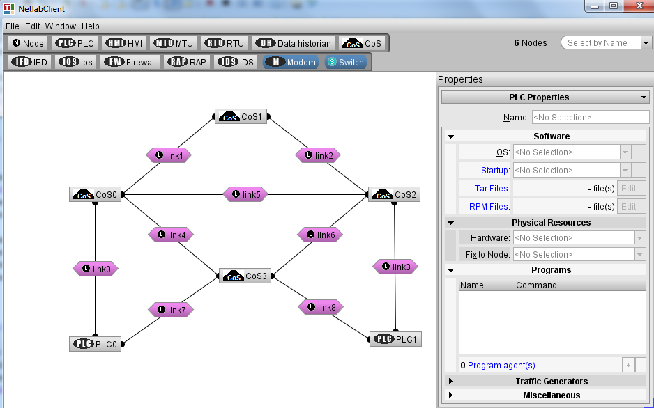
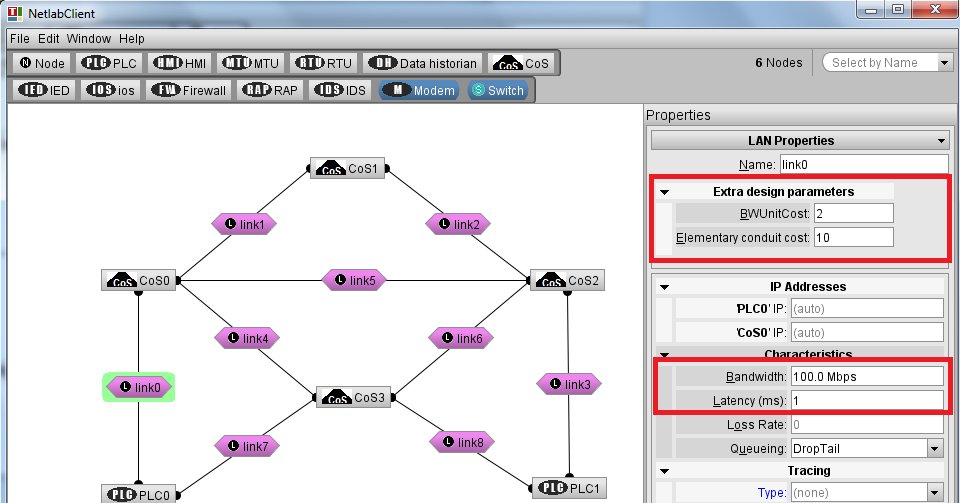
- Start the NetLab client and build the network topology as shown below. This topology includes 4 CoS (Concentrator Sites), 8 links, and 2 PLCs. The aim of the network design is to find the optimal selection of links and CoS such that the total cost of the installation is minimized (for a complete description of the design problem see the paper Cyber-Security-Aware Network Design of Industrial Control Systems).
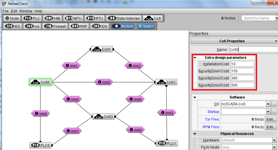
- For each CoS we need to configure: the cost of installing the node and the cost of installing security zones in its premises (the remaining parameters, e.g., Startup, are not used by the NetworkDesign software - these are specific to the Emulab testbed, and will be removed in future software versions). In the present software version only 3 security zone levels are supported. We assume that the installation cost is the same for all CoS (as shown in the figure below).
- For each link we need to configure: the cost of one bandwidth unit, the cost of elementary security conduit, the available bandwidth, and the link latency.
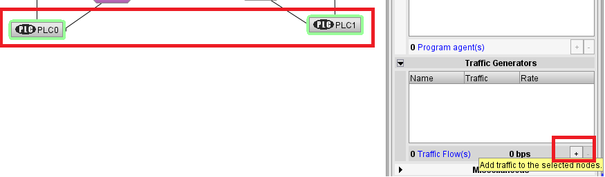
- Next, we define the traffic that is routed between end-points (e.g., PLCs in this example). We select the two end-points (PLC0 and PLC1) and we add a traffic generator, as shown in the figure below.
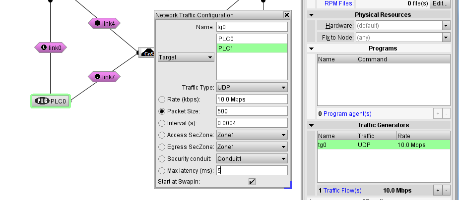
- By double-clicking on the traffic generator, we are able to configure the generated traffic and its security and quality requirements (see the figure below). We configure one traffic (flow) of 10Mbps that needs to be routed from PLC0 to PLC1. We assume that the access end-point (PLC0) needs to be placed in a Security Zone of at least level 1, while the egress end-point (PLC1) needs to be placed in a Security Zone of at least level 2. The flow requires a security conduit of at least level 1. The maximum allowed latency is of 5ms.
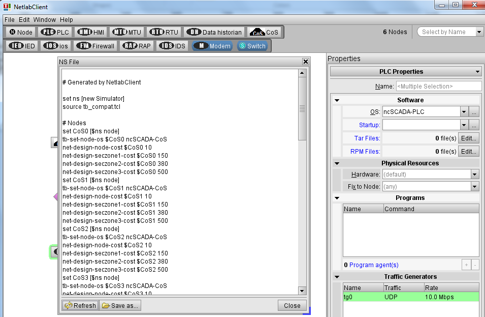
- Lastly, by selecting in the Window menu the NS file option, we visualize the generated description. Here, we select the refresh button to ensure that the latest values are shown in this windows. Then, the configuration is saved by selecting the "Save As" button in the "network.ns" file.
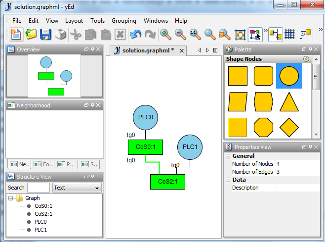
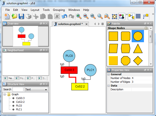
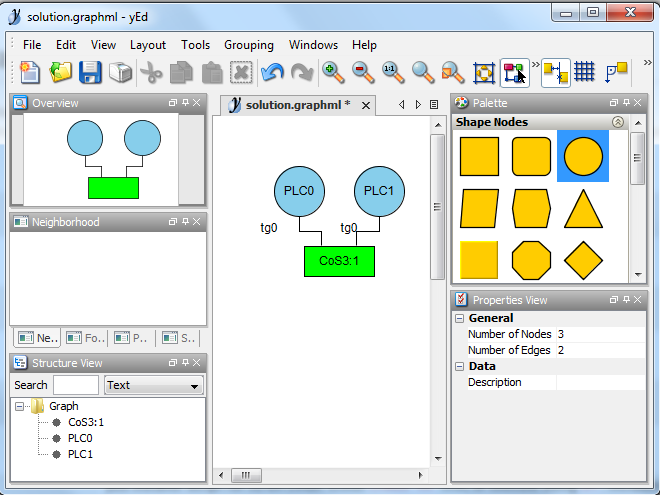
- Once the network topology is saved, we can start the NetworkDesign software. By default, it takes as input file the "network.ns" file and it generates the solution in the "solution.graphml" file. The generated GraphML file can then be visualized with the yED graph editor. Since the generated GraphML file does not contain valid positions of objects, once the file is opened, we can change the layout from the "Layout" menu to ensure a comprehensive visualization.
myuser@ubuntu:~/NetworkDesign$ ./NetworkDesign.py -s /home/myuser/scipoptsuite-3.2.0/scip-3.2.0/bin/scip
*** The solution of the optimization is:  [(1, 1), (5, 1), (9, 1), (29, 1)]
*** The mapping of the solution:  ({}, {'tg0': ('CoS3', 'PLC0')}, {'tg0': ('CoS3', 'PLC1')}, [('CoS3', 1)], [])
*** The solution was written to:  solution.graphml
myuser@ubuntu:~/NetworkDesign$ ./NetworkDesign.py -s /home/myuser/scipoptsuite-3.2.0/scip-3.2.0/bin/scip
*** The solution of the optimization is:  [(2, 1), (4, 1), (8, 1), (10, 1), (26, 1), (32, 1), (38, 1), (54, 1)]
*** The mapping of the solution:  ({'tg0': [('CoS0', 'CoS2')]}, {'tg0': ('CoS0', 'PLC0')}, {'tg0': ('CoS2', 'PLC1')}, [('CoS2', 1), ('CoS0', 1)], [(('CoS0', 'CoS2'), 1)])
*** The solution was written to:  solution.graphml